The KAS Lock-S Software must be activated with Serial number and Product ID. The authorized client must safeguard the unique Product ID assigned. An authorized person should be assigned to take custody of the Product ID and take measure not to disclose to unauthorized persons. Damages caused to the client or any other party due to disclosure of Product ID shall be liable to the client solely; the manufacturer and representative should not be held liable whatsoever. In case such incident shall cause any damage to the manufacturer or representative, right is reserved to claim for compensation.
1. Supervise, manage and train front desk staff to use the software.
2. Responsible for database backup and maintenance.
3. Create and assign Roles for staff per the business requirements.
1. All locks have been installed on doors, all rooms have been assigned, and required staff roles have been created and given the correct permissions.
3. Ensure hotel management has designated all rooms and configured any necessary zoning (e.g. Housekeepers, service zone, floor zone, common door zone or lift zone etc.)
4. Confirm building designation (for multiple buildings managed by same computer), floor numbering, room numbering and room type.
5. All accessories are ready (e.g. Card Encoder and blank cards)
1. To execute the software, double click on the shortcut icon.
2. Select ‘SQL Server’ for database type and enter the previously created SQL server instance. Click the drop down to show the machine name and enter the SQL database name after the ‘\’ symbol
3. Click ‘Next’. See Figure 7
4. Enter the password which was set to access the SQL server. Default: “kas123”. Default Username: "SA". See Figure 8.
5. Click ‘OK’
1. Take note of the ‘Application-ID’ and contact KAS to receive your software serial number. See Figure 10.
2. Enter the serial number into the 6 blank boxes and click ‘Next’. See Figure 11.
3. Enter the name of your property. This field is optional and can be modified later. See Figure 12
4. The Registration and SQL Server connection wizard is complete. Click ‘Finish’ to launch the full application. See Figure 13
After complete the previous steps, you will be taken to the login screen, Figure 14. The login screen will be displayed every time you launch the application. At this point only the System Administrator can log on with the default username and password.
User Name: admin
Password: 123
Figure 14
Click [OK] to enter the main application.
At this stage, there is no data in the system; next steps will be to issue the System card, configure the rooms, adding users and assign user roles.
Forgot Password
In the event that a user has forgotten their password
- Type in the username in the "User name" field
- Place your System Card on the reader
- Click "Forget Password"
- With the "Password" field empty, click "OK"
- You will be prompted to create a new password. Ensure that "Current Password" is empty.
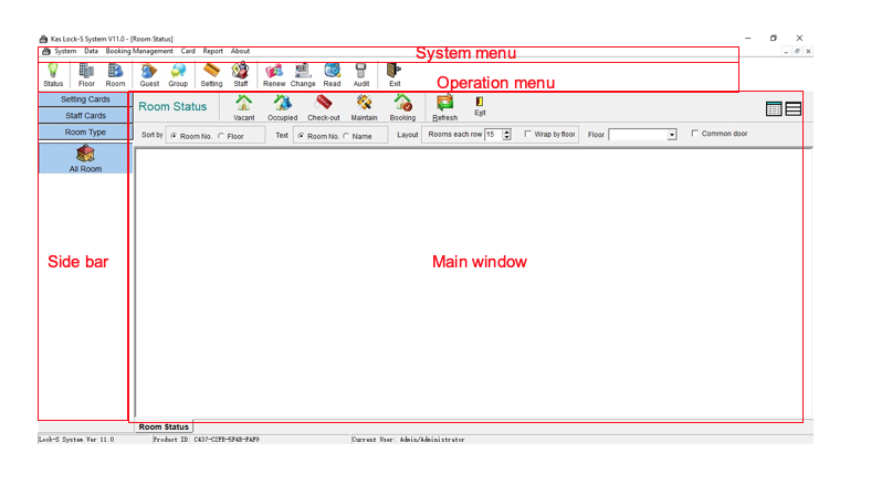
There are four main areas which will be referred to in this manual.
System Menu – Global settings and parameter setting
Operation menu – Quick selection for card reading/room setting
Side bar – Display windows to program all types of cards
Main window – Displays the current main window
Parameters and Configuration
System -> System Parameters
In the system menu, click "System" then "System Parameters" in the pull-down menu to display the System's configuration menu (Figure 15).
Property Name: The property's name
Management Model:
- Hotel Mode - Sets Checkout Date 1 day ahead of the Guest Card's creation day.
- Apartment Mode - Sets Checkout Date 1 month ahead of the Guest Card's creation day.
- Best practice is to leave this on Hotel and modify the default check out time and days as desired.
Checkout Time: Default time is 12:00:00 next day, it can be changed accordingly. Time range is between 00:00:00 - 23:59:59.
Encoder Type: Leave at default
Encoder Port: Leave at default
PDA Type: Set according to your PDA Type (if using one). Contact KAS if unsure.
Default Day(s): The default length of stay when issuing Guest Cards.
Port for net message: Leave at default.
Allow Common Door Function: Check box to activate Common Door control in the software, default is non-activated, see the common door section in this manual for more information.
Allow Lift Function: Check box to active Lift control, default is non-activated, see lift section in this manual for more information.
Allow Park Function: Check box to active Parking control, default is non-activated, see Park section in this manual for more information.
Default international code: Displays default international code to send mobile keys if Bluetooth locks are installed.

Note: Bluetooth Functionality for Lock-S has been deprecated
Figure 15
Click [Apply], then [OK] to save and close the window.
Managing Roles
In the system menu, click "System" then "Roles" in the pull-down menu to display (Figure 16). The Administrator role should always have all options selected. As a default, there are 3 roles created; [Administrator], [Duty Manager], [Reception]. You can create additional roles in the [Other] tab.
 [Administrator] roles cannot be modified.
 Figure 16
Each role has different tasks which can be modified as per your requirements. Ensure to click [Apply] to save your selection. [Other] roles with different tasks can be self-defined.
Right-click in the empty window in Figure 17 and click [Add] to create a new custom role.
Enter a user and description in the pop up window and select/unselect assigned tasks for the new role. Click [OK] to save your selection. See Figure 18.
A new user role has now been created. A password for the new role still needs to be created.

Figure 17
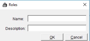
Figure 18
Managing Users
To add a new user, in the system menu click [System] then [Users] in the pull-down menu to display Figure 19. By default, the [Administrator] is already in the system.
Click [Add] to create a new user login.
Figure 19
In Figure 20, enter a user name and other fields accordingly. Click [Next] to proceed in creating a password and assigning which [Role] this user will obtain.
Figure 20
Enter a password and select [Next]. See Figure 21. Check the box IF this user must change their password at next logon.
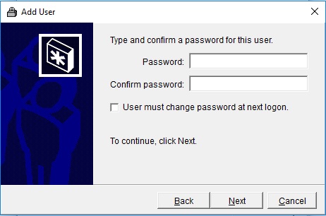
Figure 21
Assign which [Role] for the newly created user in Figure 22. Click the [Other] radio button to select a custom user role. If the role of the user is not available in the list then go back to Managing Roles and ensure the new role is created successfully.
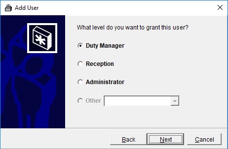
Figure 22
Click [Next] and check any additional card read/write authorization for this user. This defines what action this user can perform with cards. See Figure 23.
Figure 23
Click [Finish]
Select the user so the row is highlighted in a blue shade. Then click [Property] and Figure 24 will appear.
Figure 24
Edit the User Properties such as; name, description, passwords and role privileges. The [Administrator] can disable users and unlock user accounts if it has been locked by the user (entering password wrong too many times). Select [Delete] to delete the user permanently from the software. See Figure 19.
Note: The [Administrator] role cannot be deleted and none of its property roles can be changed.
Modify [Administrator] password:
While logged in as the Administrator:
- Select "System" in the system menu.
- Select "Change Password"
Note: This applies to users who wish to change their own password, too.
Modify User password:
To change a user's password for them, while logged in as the Administrator:
- Select "System" in the system menu.
- Select "Users"
- Select "Set Password" (figure 25)
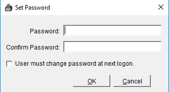
Figure 25
Managing Floors
From here on the software rooms will be configured.
In this example, a property has 2 buildings designated as 01 and 02 respectively. Building 01 has 20 floors of guest rooms, floors 1-10 are all single rooms, floors 11-18 are double rooms, and floors 19-20 are deluxe suites. Building 02 has 3 floors, each floor has 8 rooms which are all office rooms.
The following steps will configure the property based on the above information. The KAS Lock-S System will designate a room number with 6 digits as depicted below:
Build Floors Wizard
In the system menu, click "Data" then "Floor" in the pull-down menu. See Figure 26.
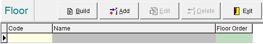
Figure 26
Start Order determines the floor ordering number i.e. ‘1’ and Start Floor determines the starting floor number i.e. ‘1’. See Figure 28.
Click [Next}, enter the Number of floors for the property. Default value is 20, change with up and down arrows and directly type in a value. See Figure 29
Click [Next], and check your generation before proceeding, see Figure 30. If ok, click [OK]. If some edits are required, select [Back] to modify.
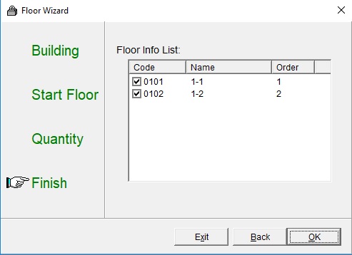
Figure 30
Modify floors manually
Other than generating floors in batch, a user can also Add, Edit or Delete a floor, click [Add] , [Edit] or [Delete] button the window pop up will have [Save] and [Cancel] buttons. See Figure 26 and Figure 31
Enter correct Code, Name and Floor Order.
Click [Save] to save the added floor.
Figure 31
Edit Floor:
Highlight floor to be edited, click [Edit].
Edit data when necessary, click [Save] to save changes, click [Cancel] to abort action.
You can modify Code, Floor Order and Name without needing to change door programming.
Delete Floor:
Highlight floor to be deleted, click [Delete];
A confirmation message will pop up.
Click [Yes] to confirm delete floor, [No] to abort action.
Set Room Type
Add room type
In the system menu, click [Data] then [Room Type] in pull down menu;
A user can [Add], [Edit] or [Delete] a room type, since there is no room type yet [Edit] and [Delete] are not applicable, see Figure 32.
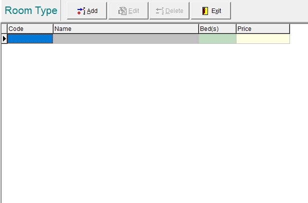
Figure 32
Click [Add] and the room type window will pop up, see Figure 33.
Enter any Code and the Name of the room type, for example “Standard”, “Double Room”, “Studio” etc. Beds and Price fields are optional.
Click [Save] to save your selection.
Add as many Room Types as desired and now proceed to creating rooms.
Figure 33
Edit room type
In the room type list highlight the room type to be edited. Click [Edit] the window pop up will enable [Save] and [Cancel] buttons.
Edit data of this room type, example here to change number of beds; click [Save] to save changes and [Cancel] to abort action.
Delete Room Type
In the room type list highlight the room type to be deleted. A confirmation message will display.
Click [Yes] to confirm delete floor, [No] to abort action.
Use the follow steps to launch the create Guest rooms wizard.
In the system menu, click [Data] then [Guest room] and Figure 34 will appear.
Figure 34
Click [Build] and the room build wizard window will appear, see Figure 35
Figure 35
Click [Next] to build Guest Rooms then use the drop-down field to select the Room Type and Floor, see Figure 36.
OR
Select ‘Build Office’ radio button to build a series of Office doors.
Staff cards will only open Office doors. Similarly, Guest cards will only open Guest Rooms (and common doors). Figure 36
Click [Next] then define the starting from number and to the ending number of guest rooms on this floor, see Figure 37. It can be 1, 2, 3 or maximum 4 digits. If using a single digit like 1 digit or 3 digits as starting number,
It will automatically suffix the number with a 0. If using multiple digits like 2 or 4 as starting number, it will not suffix or prefix the number. In most cases use a 2-digit room number on each floor. The system will automatically add building number and floor number: so you keep the room number pattern consistent – as described in room format image below:
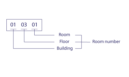
Please note: the room number can does not have to be the same as the above format.
The building wizard will force this format but if you wanted a completely different room number structure, you are welcome to manually create/edit each room. i.e Rooms 1-40 have the room numbers “01-1,01-2,01-3,…,01-30” if you desire.
N.B If you edit the following fields, you do NOT have to re-program the doors; Lock No., Lock Name, Room Type, Auto Open, Open Time. If you edit the Floor field, you will need to re-program the door lock.
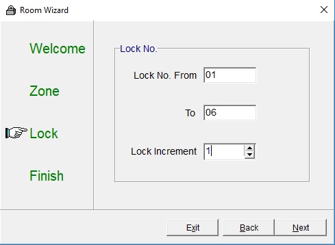
Figure 37
Enter the number of locks per floor. You can also append and remove locks later if you wish.
This example is 6 locks per floor; ‘01’ to ‘06’.
Lock Increment is the step between each lock. Leave this field as ‘1’ unless required otherwise.
Click [Next], and Figure 38 will appear. Check the Guest rooms in the list to make sure they are correct, click [OK] to confirm and save data.
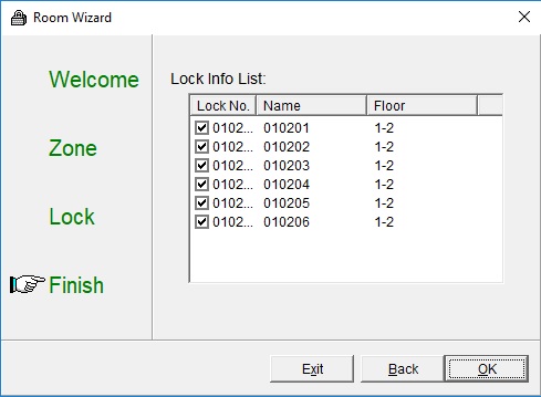
Figure 38
The software will prompt if the rooms have been built correctly, click [Yes] to confirm. See Figure 39
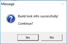
Figure 39
Edit Room:
Highlight room to be edited, click [Edit].
Edit data when necessary, click [Save] to save changes, click [Cancel] to abort action.
Note: You can modify Lock No., Lock Name, Room Type, Auto Open and Open Time without needing to change door programming.
Highlight room to be deleted, click [Delete];
A confirmation message will pop up.
Click [Yes] to confirm delete floor, [No] to abort action.
Manage Common Rooms
Common Rooms are rooms that have shared access between guests and staff (e.g. Laundry, gym, pool).
In order to have Common Room Functionality, ensure that it is enabled:
- Select "System" in the system menu
- Select "System Parameters"
- Ensure "Allow Common Door Function" is ticked
- Click "Apply" and then "OK"
Creating a Common Room:
- Select "Data" in the system menu.
- Select "Common Door"
- Click "Add"
- Configure the door as required:
- Code: Leave it as default, this is usually set automatically by the system
- Name: Common Door's name
- Floor: What floor is belongs to (Can only be set if Floors have been configured)
- Auto Open: Designate a time for the door to automatically open to everyone (e.g. Front reception door)
- Open Time: Designate a time window for the guests to be able to open the door (e.g. a gym)
- Default Authorization: Whether or not a Common Door will automatically be selected when creating a card that can have Common Door access
- No Guest Card Enter: Whether or not a Guest Card can open this Common Door (e.g. if you want staff-only common rooms)
- Click "Save"
Note: When a Common Door is on a floor (e.g. 5th floor), all guests with access to that common door access will also have access to that floor.
If there are office rooms to be controlled by the same system, configuration is the same procedures as Guest rooms. Click [Data] then [Office] and proceed as building guest rooms. See Figure 40.
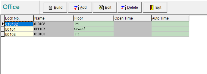
Figure 40
Managing Lock Layers
Note: If the guest can get to their room door which is not layered inside other door access, that room does not need to be layered, skip this section.
Setting Layer Structure
In the system menu, click [Data] then [Layer] in pull down menu, Figure 41 will appear.
From the room list, drag Room A to Room B then Room A will be set as the sub-layer of Room B.
Any card issued to a sub-layer lock can open its upper layered lock. The upper layer lock although has a room number the system will not issue individual key cards to it, only to its sub-layer locks.
Note: You can also layer Office doors.
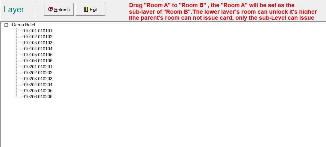
Figure 41
Adjust Layer Structure
In Figure 42, room ‘010102’ has been dragged as sub-layer to ‘010101’ which is the upper layer, to change just drag and drop again or highlight room number then right click to popup menu with 3 actions and click the appropriate one, see Figure 43.
Note: You can layer rooms infinitely. As long as rooms share the same Floor.
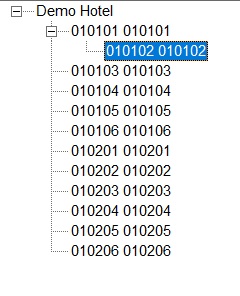
Figure 42
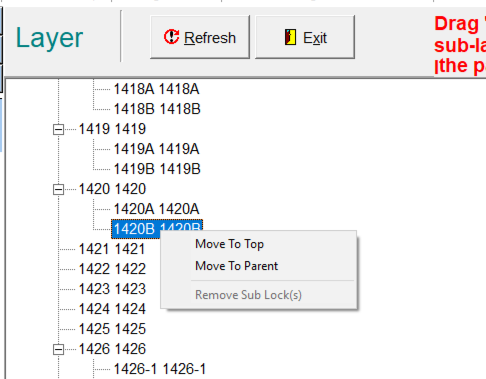
Figure 43
Room Status Query
After the hotel has been configured, log out of the system; at next log on the room status window will display; click [Report] then select [Room Status] will also come to this windows. See Figure 44
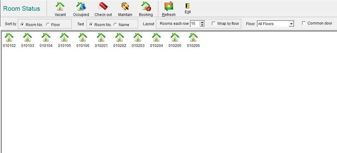
Figure 44
Display by Room Type: On left column in this window all room types set earlier will display, click any guest room type will show only rooms that fall under that particular room type. Clicking [All Room] will show all guest rooms, clicking [Office] will show all office rooms.

Figure 45
Display by Room Status: After display under room type, more criteria are shown on top bar see Figure 45, click on the icon to show rooms that meet other particular criteria such as vacant rooms, occupied rooms, checked-out rooms, rooms under maintenance and rooms with bookings.

Figure 46
To set room to Maintain status, right click on room and click on [Set As Maintain], the room status should now be set as Maintain see Figure 46. To set status back to Vacant, right click on the room, click on [Set As Vacant].
Note: User can carry out key card operations when right clicking on rooms in the room status window, key card operations include commands like [Issue Card], [Group Card], [Renew] and [Change Room]. These commands are also available from the main menu.
Before issuing cards, the following is a general layout of the operation window.
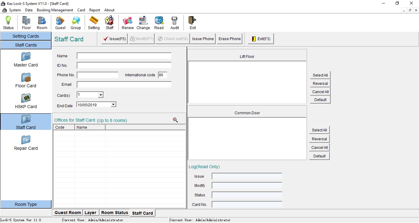
Figure 47
Main Menu Icon: All software functions are available from the Main Menu by clicking on an icon a drop down menu will appear.
Main Tools: Some frequently used functions available by clicking the icons in the main tools bar.
Sub Menu: After clicking the icons in main menu or main tool bar sometimes further selection from sub menu bar is needed to access the corresponding window;
Data Fields: Detail fields of information, some are default and cannot be changed.

Figure 48
Multi-windows bar: Multiple-windows can be opened during system operation, clicking on different tabs in the Multi-window bar will select and display different windows see Figure 48.
Status bar: Shows some system information like software version number, Product ID, and current logged on user.
After completing the above procedures, the software settings and configurations are completed. However, the locks are not yet recruited by the software system, the next section will encode/program the physical door locks.
A Project Card prepared by KAS maybe be shipped with the locks so that during construction period locks installed and powered can be opened by this card until the locks are encoded by the System Card and Parameter Card.
Project cards become void after locks has been encoded.
Encoding and access control of door locks are realized by issuing different cards.
Note: While they can still be provided, Project Cards have been deprecated. It is recommended to issue a Master Card during construction to allow workers to access rooms.
Setting Cards
These include System Card, Parameter Card, Clock Card, Meeting Card, Inhibit Card, Erase Card, Query Card and Remote Card.
Among them System, Parameter and Clock Card must be issued at first to encode the door locks.
Other cards can be issued as required.
Access to Setting Cards are found in the following areas:
- By clicking on the "Setting Cards" button found on the menu bar in the left-hand window.
- By clicking "Card" in the system menu, and then "Setting Card"
- By clicking the "Setting" icon at the top menu bar
Staff Cards
These include Master Card, Floor Card, HSKP (housekeeping or cleaning) Card, Staff Card and Repair card (for offices). These are for hotel staff; issue them after System Card and Parameter Cards have been issued.
Access to Staff Cards are found in the following areas:
- By clicking on the "Staff Cards" button found on the menu bar in the left-hand window.
- By clicking "Card" in the system menu, and then "Staff Card"
- By clicking the "Staff" icon at the top menu bar
Guest Cards
These are for hotel guests, issue them after System Card and Parameter Cards have been issued.
Access to Guest Cards are found in the following areas:
- By clicking on the "Room Type" button found on the menu bar in the left-hand window
- By clicking "Card" in the system menu, and then "Guest Card"
- By clicking the "Guest" icon at the top menu bar
By clicking on [Card] from the main menu then [Guest Card], OR click [Guest] icon from the menu bar, OR double clicking on a room shown in the Status window.
Note: Group Card, Renew and Change are applicable to guest cards only.
Issuing Cards
System Card
Note: Each system set up can only issue one system card and should be kept safe by management after use.
The System Card is used to both reset the programming on a lock, and to put it into programming mode to accept Parameter Cards
A System card generated is unique to the system, all locks programmed by one system card will not respond to another system card. A new lock must be encoded by the system card before it will accept any other card.
Select "Setting Cards" and then "System Card" (Figure 49)
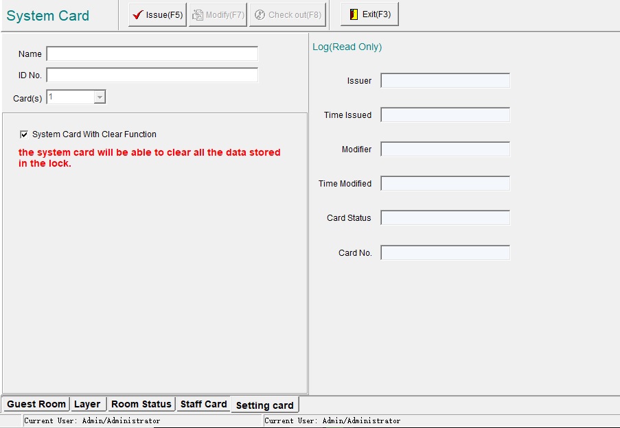
Figure 49
Optional: Enter the name and ID Number of the card holder for record keeping.
System Clear Function: Ticking this box will allow the System Card to erase a lock's programming. This should be used with caution, as it is very common to accidentally erase a lock's programming when trying to set it. It is recommended to not have this function ticked unless necessary.
A System Card can only clear a lock that has been programmed by the same card. In order to clear a lock that has been programmed by a different system card (e.g. if your computer has failed and you had to re-install your Lock-S software on a new computer), the lock will have to come off the door in order to be physically reset by a button in the back.
To issue a system card:
- Place a card in the card encoder and click [Issue].
- If a card had been used before and still contain valid data the system will prompt and ask to confirm before erasing the old card data, click [Yes] to confirm.
- After a successful confirmation message appeared, remove the card from the card encoder and you have successfully created a System Card.
It is recommended to write "System Card" on the card, and keep it in a safe place away from staff unless it is needed.
Parameter Card
A Parameter Card is used to tell a lock which room / door it belongs to.
After a System Card is issued, Select "Setting Cards" and then "Parameter Card". (Figure 50).
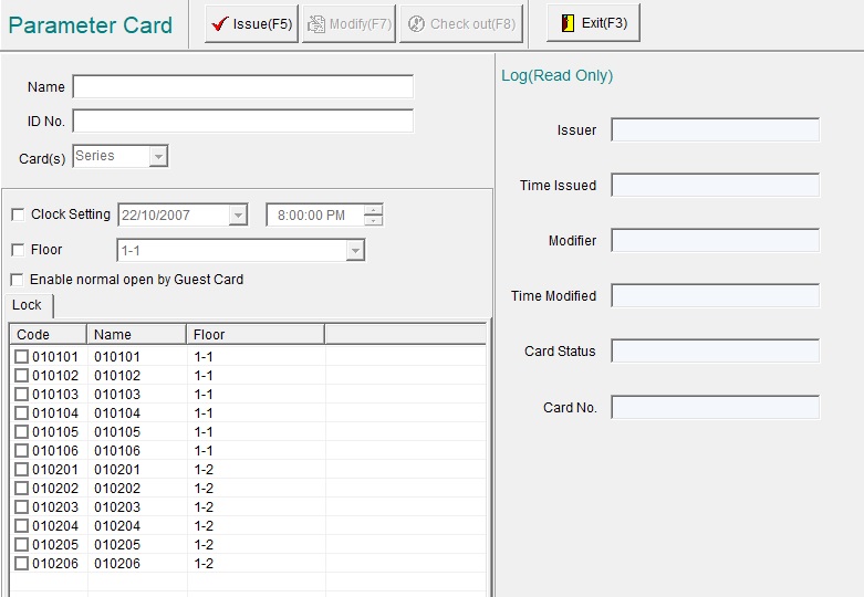
Figure 50
Optional: Enter the name and ID Number of the card holder for record keeping.
To issue a Parameter Card:
- Place a card on the card reader.
- Check the tick-box next to Clock Setting to transfer PC time to the lock (This is optional - But negates the need for a Clock Card).
- Tick the room you wish to Parameter Card to program. (Note: Multiple rooms can be selected, however only 1 room can be programmed on each card. When selecting multiple rooms, the system will ask for a new card between each room).
- The "Lock" submenu has guest rooms, as well as office rooms.
- The "Door" submenu has common doors.
- The "Lift" submenu has lifts.
- The "Park" submenu has parking access.
- Click "Issue". If the card is already used, the system will ask if you wish to overwrite it. Click "Yes" or change to a blank card. See Figure 51.
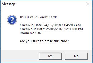
Figure 51
If only one lock is selected, a remove card message will appear after encoding is completed. See Figure 52.
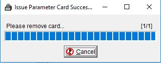
Figure 52
If multiple locks are selected, a remove message will appear after encoding a card is completed and the progress bar will stop and wait for the next room's card, remove the card from the encoder and present the next card.
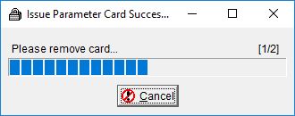
Figure 53
Note: If programming a large number of rooms, it is recommended to NOT use the "Clock Setting" option, as by the time you would have finished all of them it would be out of sync. Use a Clock Card separately when programming a large number of rooms.
To program a door with the Parameter Card:
- Take your System Card, Parameter Card, a Guest/Staff card (depending on the door type), and a Clock Card (*optional: Not necessary if you used the "Clock Setting" function)
- Present the cards to the lock in the following order: System Card -> Parameter Card -> Clock Card* -> Guest/Staff card
- The lock should sound a single beep after each card, and the door should unlock to the Guest/Staff card.
A clock card tells each lock it's presented to what time it is at the time of the card's creation.
Select "Setting Cards" and then "Clock Card". (Figure 54).
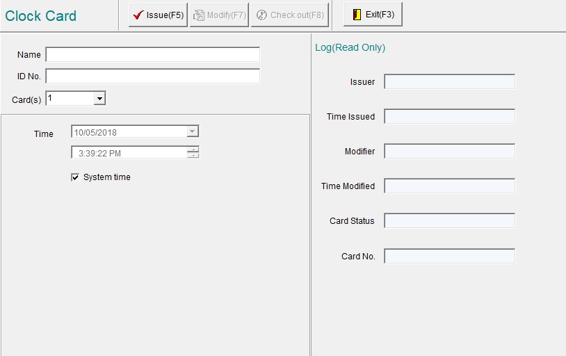
Figure 54
Optional: Enter the name and ID Number of the card holder for record keeping.
Time: Sets the Time & Date to match the computer. You may set this manually if you wish by unticking the "System Time" box.
Creating & Using a Clock Card:
- Place a card on the reader
- Click "Issue"
- If the card is already used, the system will give you the option to overwrite it. Click "Yes" or place a blank card.
- Present the Clock Card to the desired lock.

A Clock Card will have the time of when it was created. DO NOT reuse clock cards without re-issuing them, as they will hold an older time & date.
This also applies if setting the clock to a large amount of locks. Re-issue the Clock Card after each batch of locks (e.g. between each floor).
Master Card
A Master Card will always open a lock, regardless of the time, date, or the position of the Privacy Latch.
Select "Staff Cards" and then "Master Card". (Figure 55).
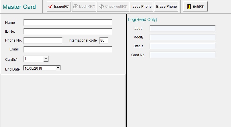
Figure 55
Optional: Enter the name, ID Number, email, and Phone Number of the card holder for record keeping.
End Date: The date at which the Master Card will expire. This is useful if, for example, workers need access to all the rooms during construction.
Issuing a Master Card:
- Place a card on the reader
- Click "Issue"
- If the card is already used, the system will give you the option to overwrite it. Click "Yes" or place a blank card.
Note: The system allows issuing multiple Master Cards, however for the sake of security it is recommended not to have more than 3 Master Cards. Same with expiry date, the shorter the validity the more secure it is. Management has to balance the risk level vs. convenience.
Floor Card
Floor Cards can access all doors on one level, regardless of the time. They cannot override the privacy latch.
Can be used in conjunction with a Meeting Card to set a lock into Free Passage mode.
Can access Common Doors if selected.
Select "Staff Cards" and then "Floor Card". (Figure 55).
Figure 56.
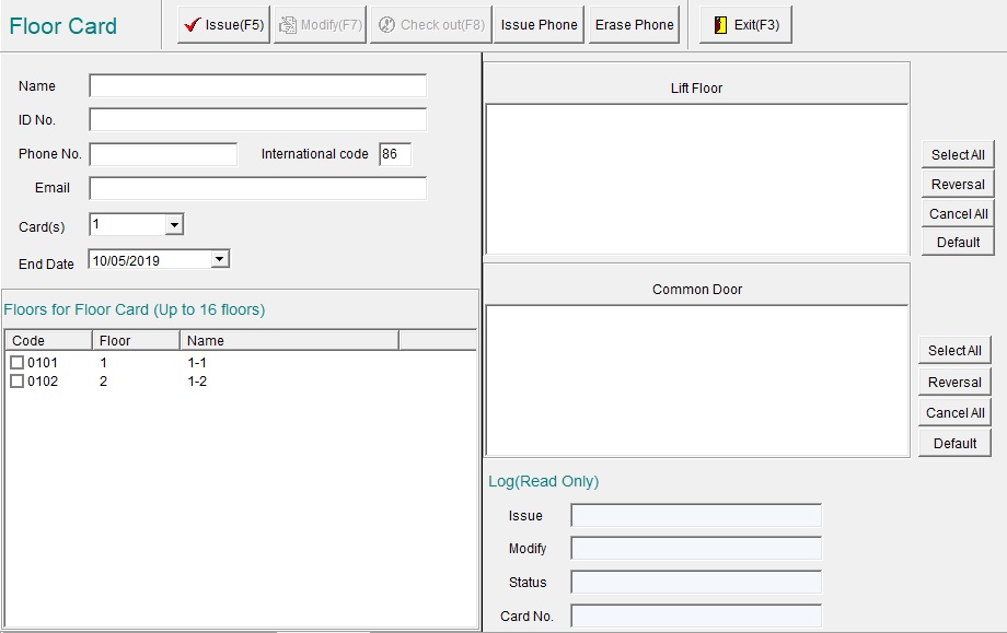
Figure 56
Optional: Enter the name and ID Number of the card holder for record keeping.
Issuing a Floor Card:
- Place a card on the reader
- Select which floors you wish it to access (Multiple floors are allowed) and any Common Doors you desire.
- Click "Issue"
- If the card is already used, the system will give you the option to overwrite it. Click "Yes" or place a blank card.
Housekeeping (HSKP) Card
Housekeeping Cards can access all locks on same floor level within the designated time window. Cannot override privacy latches. Can access Common Rooms if selected.
Select "Staff Cards" and then "HSKP Card". (Figure 57).
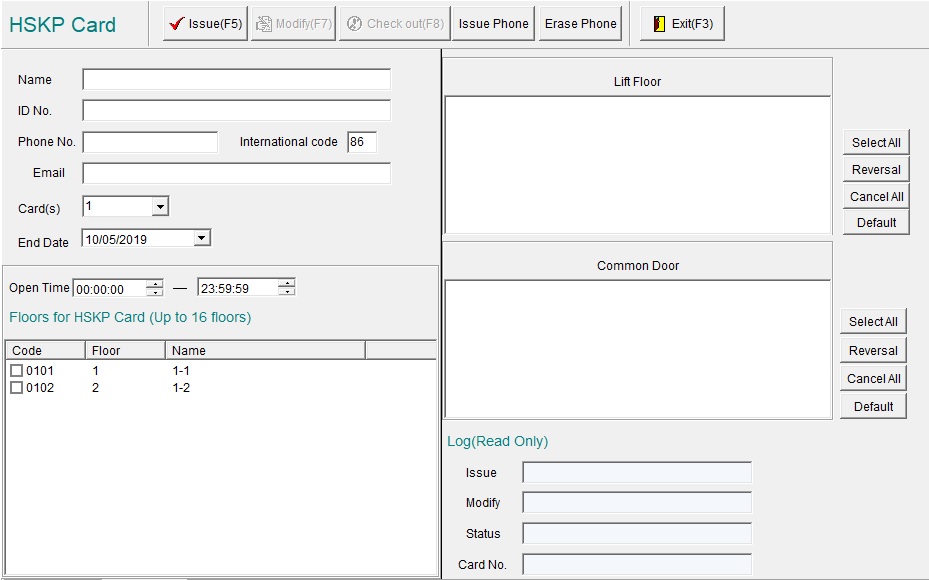
Figure 57
Issuing a Floor Card:
- Place a card on the reader
- Select the End Date of the card (expiry)
- Select the Open Time (Time window where the housekeeping card will open the doors)
- Select which floors the housekeeping card is applicable to (Multiple floors are allowed), and any Common Doors
- Click "Issue"
- If the card is already used, the system will give you the option to overwrite it. Click "Yes" or place a blank card.
Note: Regarding common doors, HSKP Card is valid until midnight on the expiry date.
Staff Card
Staff Cards give access to office doors regardless of the time or date. They cannot access Guest Rooms or ignore Privacy Latches.
Select "Staff Cards" and then "Staff Card" (Figure 58).
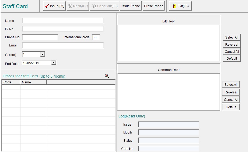
Figure 58
Optional: Enter the name and ID Number of the card holder for record keeping.
Issuing a Staff Card:
- Place a card on the reader
- Set the End Date (expiry)
- Select which Office doors the card will open (Multiple doors are allowed)
- Click "Issue"
- If the card is already used, the system will give you the option to overwrite it. Click "Yes" or place a blank card.
Guest Card
Guest Cards can access their guest room door during valid check-in period. They cannot override the privacy latch. Can access Common Doors if selected.
- Select "Room Type" in the left-hand window, select the appropriate room type (default: "Guest"), and select the room you wish to issue a Guest Card for.
- OR click the "Guest" button on the top menu (Figure 58).
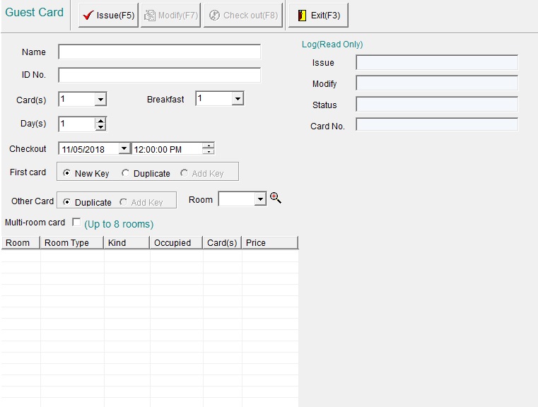
Figure 59
Optional: Enter the name and ID Number of the card holder for record keeping.
New Card means this card will replace and invalidate previously issued key cards to this room.
Duplicate Card means this card has same authorization and check-out time as previously issued card to this room and previously issued key cards will still continue to function.
Issuing a Guest Card:
- Place a card on the reader
- If the room isn't already on the list, select it from the "Room" drop-down menu (See: Figure 60)
- Fill in the "Checkout" date & time
- OR simply select "Day(s)". This will use your predefined default checkout time.
- Optional: Fill in the "Checkin" date & time. By default this is the current day & time.
- Select how many "Card(s)" to issue (e.g. if several guests for the same room need cards)
- Optional: Select "Multi-Room card" if the guests have multiple rooms they have access to. Ensure they are on the list as mentioned in Step 2.
- Select any Common Doors the guests should have access to.
- Click "Issue"
- If more than 1 cards were selected to issue, the system will prompt you when to place the next card.
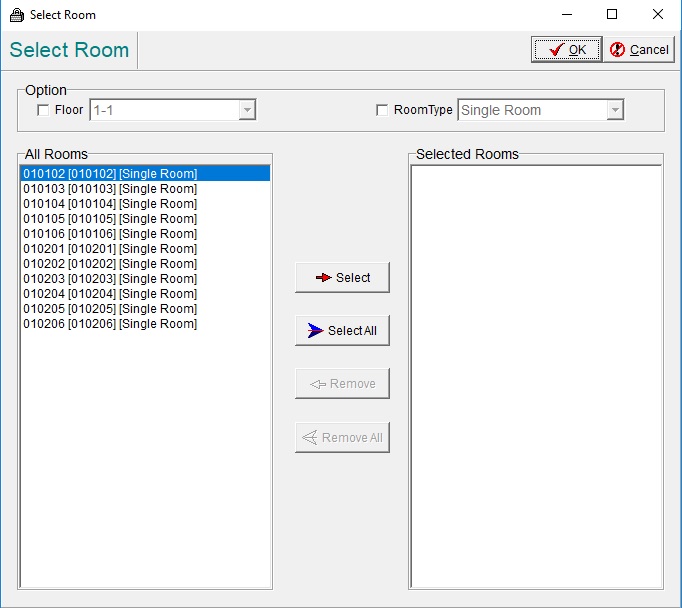
Figure 60
Note: For common doors; the guest card will still be valid after check-out time until midnight of the same date. With layered locks like common door suite, one guest card can open higher layer lock as well as lower layer.
Issuing Meeting Card
Meeting Card
A Meeting Card, sometimes referred as passage card, can set door locks into free passage mode which allows anyone to open the door without a card.
To use a Meeting Card to set it into Free Passage mode:
- Present a Floor Card to lock and wait for an audible tone
- Present the Meeting Card
To revert back to lock up mode present the Meeting Card again.
Select "Setting Cards" and then "Meeting Card" (Figure 61).
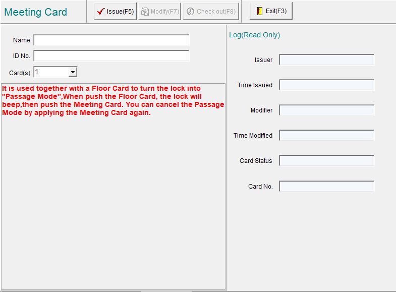
Figure 61
Optional: Enter the name and ID Number of the card holder for record keeping.
Issuing a Meeting Card:
- Place a card on the reader
- Press "Issue"
Inhibit Card
Inhibit Card sets a lock in suspended mode to deny access to any card other than the Master Card.
To revert lock back to normal mode, present the Inhibit Card again.
Select "Setting Cards" and then "Inhibit Card" (Figure 62).
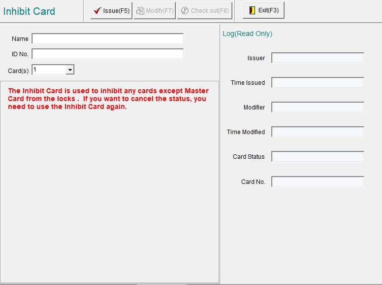
Figure 62
Optional: Enter the name and ID Number of the card holder for record keeping.
Issuing an Inhibit Card:
- Place a card on the reader
- Press "Issue"
Erase Card
Erase Cards cannot access rooms, they are used to erase a card (or type of cards) from the lock (e.g. when a Guest has lost a card, left early, or another card such as a Master Card has been lost).
Select "Setting Cards" and then "Erase Card" (Figure 62).
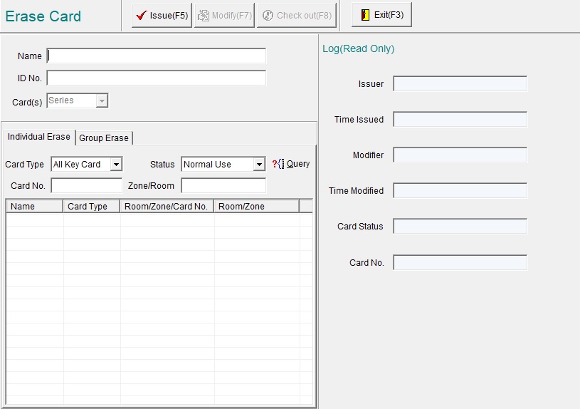
Figure 63
Optional: Enter the name and ID Number of the card holder for record keeping.
Individual Erase: Erase a single card from a lock
- Select "Card Type"
- Select "Status" (default: Normal Use, unless it was marked as Lost/Damaged in "Card -> Lost and Damaged")
- Click "Query" to present a list of all the locks of the selected type & status
- Tick the card you wish to erase
- Under "Suit" select the door type (Room or Common)
- Place a card on the card reader and click "Issue"
- Present the Erase Card to the lock
Group Erase: Erase all of the cards from the lock of a given card type (e.g. All Master Cards)
- Select which types of cards to erase from the lock
- Place a card on the reader and click "Issue"
- Present the card to the door
Query Card
Please Note: Query cards are specialized cards (S70). They are not your standard guest cards, you will need to contact the KAS Support/Sales department.
Query Card: To download door “valid card read event” records from lock and read back into system via the card encoder.
Select "Setting Cards" and then "Query Card" (Figure 64).
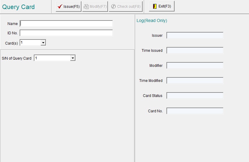
Figure 64
Issuing a Query Card:
- Place a card on the reader
- Select the S/N (Default: 1. See below for further details)
- Press "Issue"
Download and Audit Lock Open Events
- After the Query Card is issued, present the Query Card (S/N 1) to the lock you wish to download the audit logs from.
- The first query card (S/N 1) is capable of storing 1 – 420 events, if more events are stored on the lock, use the first in conjunction with a second query card (S/N 2) to increase the storing capacity to 830 events.
- The lock will flash a green LED and a short tone will be heard. Hold the card to the lock until a long tone is heard and the LED turns off.
- Place the Query Card on the card reader
- Select "Card" from the system menu
- Select "Read Audit Trial"
- OR click the "Audit" icon at the top bar
Result window (Figure 73)
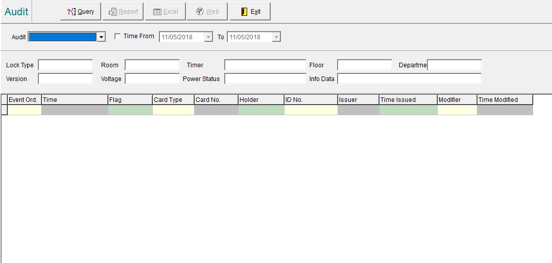
Figure 73
Note: If the Query Card presented is S/N 2 it will download from record #97 upward.
If the number of record is less than 96 the red indicator light will be on and buzzer sounds two beep to notify download unsuccessful.
If there are only a few records in the lock, the download will be quick, the green light will stays on and there will be only one long beep.
Reports
Reports will screen and display different logged data according to the selected criteria.
From the main menu click "Report", then select "Card Info" (Figure 74).
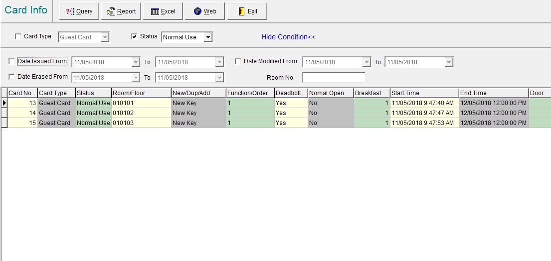
Figure 74
In the window check box next to Card Type and select Guest Card with down arrow, check box next to Status and select [Normal Use] with down arrow then click [Query], cards matching the criteria will be displayed.
If no criteria are set then all cards will be displayed.
Click [Report] icon, a preview report will be displayed and can be printed see Figure 75.
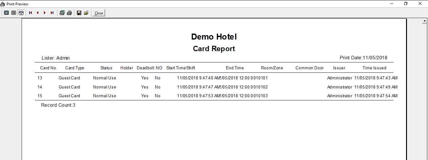
Figure 75
Clicking on the [EXCEL] icon will export the record page into EXCEL format (of course the PC must have Microsoft EXCEL installed), from the popup window see Figure 76, different columns can be selected for the EXCEL spreadsheet.
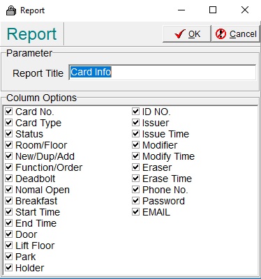
Figure 76
Clicking on the [WEB] icon will export the record page in a WEB format.
Group Card
Group Card is a function to allow the quick issue of Guest Cards in a batch.
Select "Cards" from the System Menu and then "Group Card" (Figure 65).
OR click "Group" icon at the top bar.
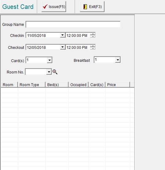
Figure 65
Issuing a Group Card:
- Type in the Group Name
- Select the "Checkin" and "Checkout" times
- Select how many "Card(s)" each room requires (this can be modified per room by Right Clicking the room on the list and then selecting "Cards")
- Select the "Room No." to add to the list of rooms to issue a card for
- Select the Common Doors that they will have access to
- Place a card on the reader and click "Issue"
- When prompted, remove the card and place a new one for the next room / person, until the process is complete.
Note: If a room is added by accident, you can select it and press "Del" on the keyboard, or Right Click it and select Delete
Read Card Data
You can read the data on a card (e.g. if you don't know which door is belongs to)
- Place the card on the card reader
- Click "Read' in main tool bar, and a window will pop up with the card's information (Figure 66).
After the card is read it can be re-formatted for other use;
- Click "Erase" to delete all data in card to make it a blank card.
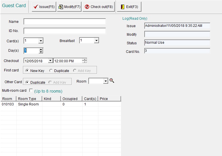
Figure 66
Modifying Card Data
The data on the card can be modified, such as: Name, Checkout dates, Common Doors, Time Setting, Clear Function on a System Card, etc.
- Click "Read" in main tool bar, and a window will pop up with the card's information (Figure 66).
- Change the details as desired and click "Modify"
For example, if a guest wishes to change their room or extend their stay:
- Place the guest card on the reader
- Select "Read" from the top menu bar
- Change the Checkout Date
- if changing a room, delete the current room from the list, and add a new one.
- Click "Modify"
Guest Check out
When guest wants to check-out at the front desk ask for their Guest Card(s).
- Place Guest Card that needs to be checked out on the card encoder.
- Click "Read" in top menu bar, the system will read data from card and display it (Figure 70).
- Click "Check Out". This will erase the Guest Card.
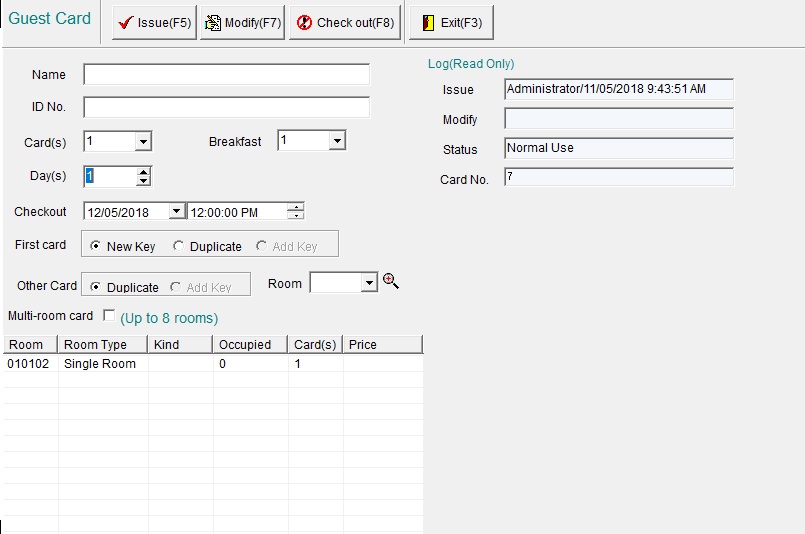
Figure 70
Lost and Damaged Card
If a guest did not return a card, or reported it lost or damaged, the card must be invalidated and erased from the door.
- Recommendation: Issue an Erase Card to remove that card from the Guest Room (see above: Erase Card) and present it to the door immediately.
- Select "Card" from the system menu
- Select "Lost and Damaged" (Figure 71)
- Tick the "Card Type" and select "Guest Card"
- Click "Refresh"
- Select the card that has been lost / damaged
- Click "Lost" or "Damaged"
- Issue a new Guest Card for the Guest (see above: Guest Card) - NOTE: Ensure you are selecting "New Key" is selected, so it will invalidate any previous keys.
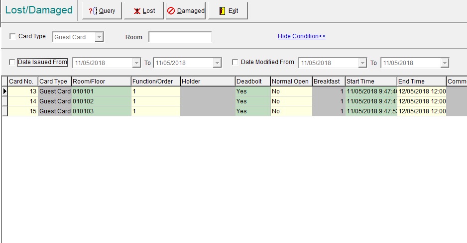
Figure 71
Booking Management
Booking a guest ahead of time via the Booking Management will show which rooms are booked for today on the Guest Room list.
Click "Booking Management" in the system menu, then select "Booking" (Figure 77).
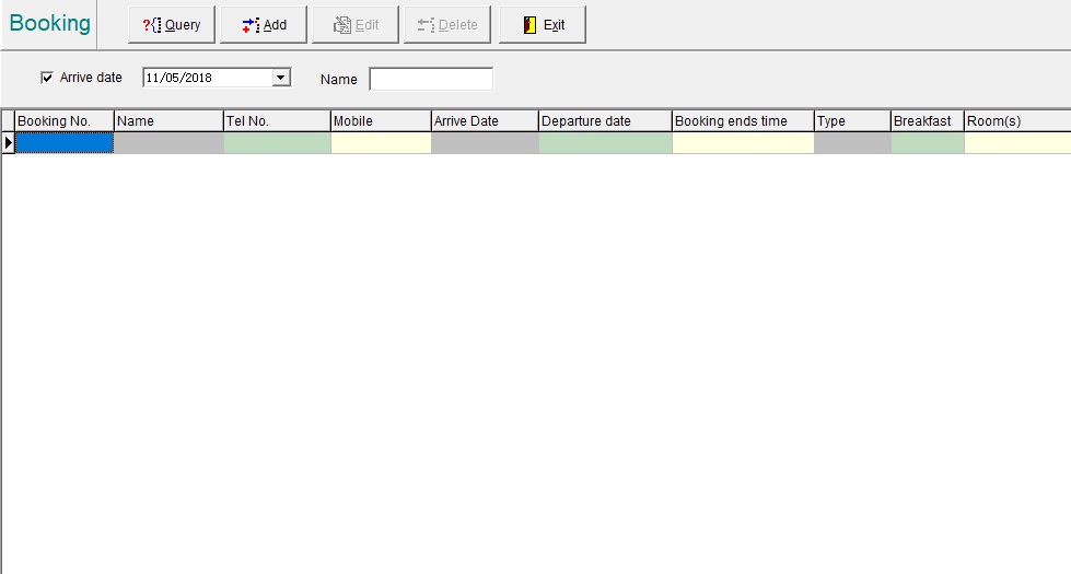
Figure 77
Click [Add] icon and input all information, make sure a Name, [Arrival Date], [Departure Date] and [Booking expiry time] are entered, click [Select Room No] to select a room from the list, multiple rooms can be selected (Figure 78).
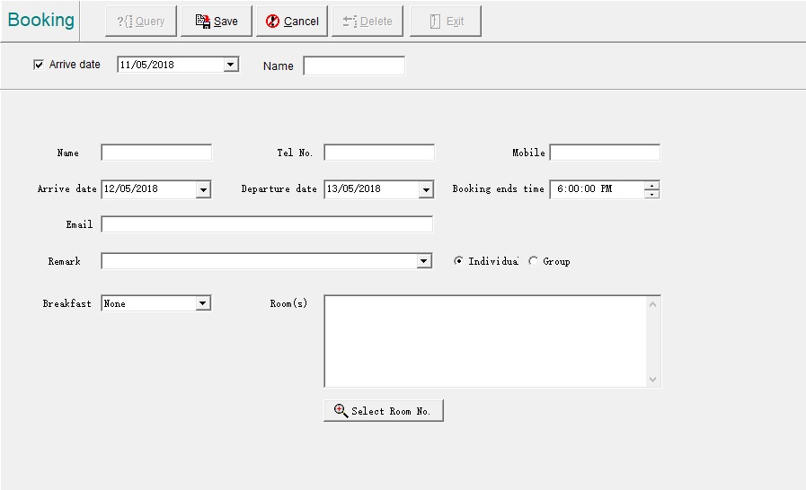
Figure 78
Click [Save], you will now return to the main booking page.
The bookings in the list can still be edited or deleted by the [Edit] or [Delete] buttons if needed.
Note: When adding a booking the system will default the arrival date to the next day, change as needed. When performing a Query, select the correct arrival date or uncheck box next to Arrive Date, otherwise the correct bookings will not show.
Reception
After a booking is confirmed by a guest and prior to their arrival date, guest cards can be issued in advance (to fast track the check in process).
Click [Booking management] then select [Reception] in pull down menu see Figure 79.
Check box next to [Arrive Date] and select date with down arrow then click [Query] icon to display the correct booking, OR uncheck the Arrive date box and input a guest name, then click [Query]. If booking is expired check the box next to [Including ended time]. Highlight the booking number and click [Issue]; card issuing steps see section 9.8.
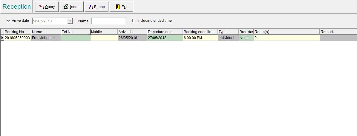
Figure 79
Others
Setting Window Background
The background graphic can be changed to any .bmp graphic file.
Click [system] then [Background] in pull drop menu see Figure 80.
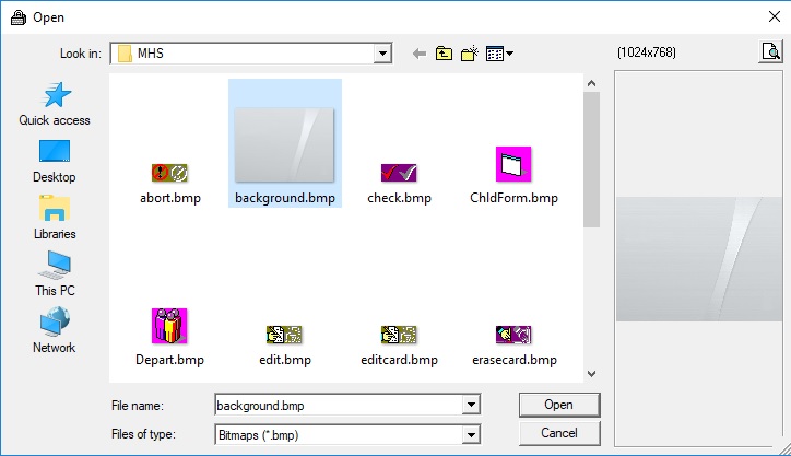
Figure 80
Select the .bmp file desired and click [Open].
Review Software Version No. and System ID
To review the current software version number and product ID, click [About] in menu bar see Figure 81.
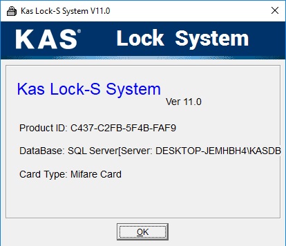
Figure 81
Software License Control
The software may have an expiry date, before the expiry date the system will prompt the user to obtain the License Code.
Click [System] then [License].
Click [Input], 4 blank fields will appear, contact manufacturer or his representative and supply the Product ID, after the License Code is given type in the fields then click [OK].
If usage of software is Unrestrained see Figure 82 then no action is required.
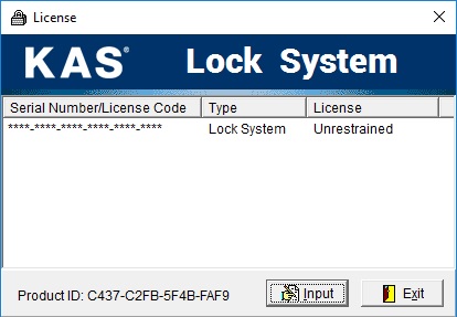
Figure 82
Database Maintenance
Database Maintenance should be performed regularly to avoid corruption caused by PC software or hardware issues.
Click [system] then [Database] in drop down menu see Figure 83.
Click [Shrink] in upper right corner, on completion click [exit]
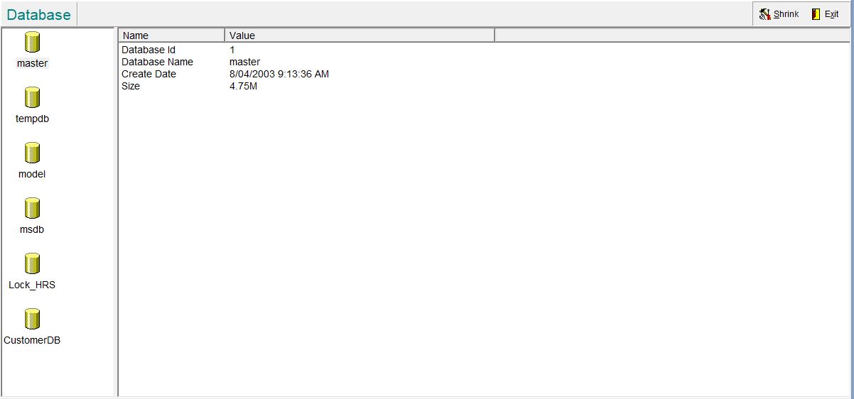
Figure 83
Adding a PIN code remotely to a NEO Lock
This option is only applicable if you have gateways installed and acticated
Note: Online functionality with Lock-S has been deprecated. While this may still work, we cannot guarantee it.
1. Open your Lock-S Software and right-click on the room that you wish to create a PIN for, select "Online Password"
2. Enter the guest's name, and the checkin/checkout dates, click "Generate"
3. A PIN code will automatically be generated. It can be used once the system reports "Success"
Setting a door to "Free Passage"
If you wish guests to access a door only at certain times of day:
- Please refer to the "Common Door" section above.
If you wish to temporarily set a door to "Free Passage" mode:
- Please refer to the "Meeting Card" section above.
Access Controls (Common Doors and Lifts)
Common Door Zone
If there are many common doors in a property a certain number of common doors can be grouped into a common door zone for easy management.
Click "Data" then select "Common Door Zone" in pull down menu:
In the Door Zone window click "Add", then input a "Code" and "Name" of this zone (Figure 87)
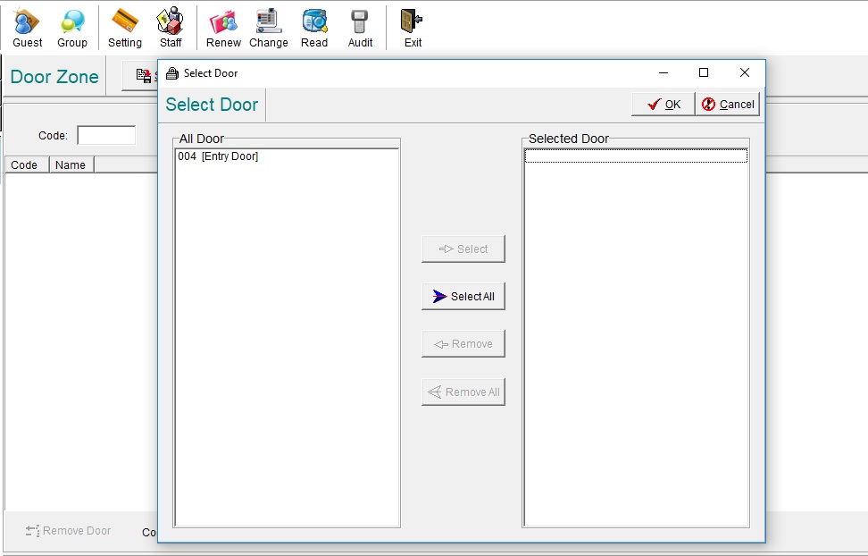
Figure 87
Click
at the bottom of the Door Zone page to popup the Select door list, "
Select" or "
Select All" common doors into this zone. Click "
Save" and back to Door Zone window.
In example see Figure 88 common doors 001 & 002 are grouped into common door zone All Doors.
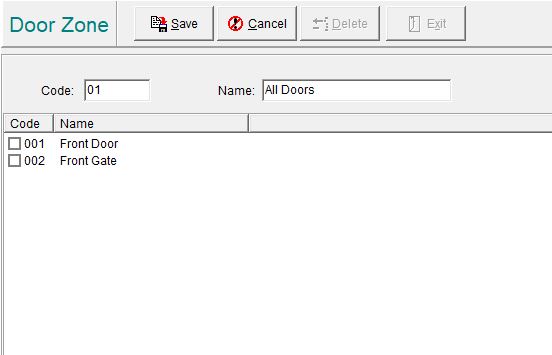
Figure 88
To "Edit" or "Delete" a common door zone, first highlight it in the list then click the corresponding icon.
Managing Lifts
To prevent unauthorized people from using the elevator(s), elevator controller(s) can be integrated with the push buttons in the elevator.
Push buttons are normally inactivated and only be activated after valid key card is presented to the reader.
Configuration of lift is similar to common door (Figure 90).
Figure 90
Enable Lift functions
Click "System" then select "System Parameters" in drop down menu (Figure 91)
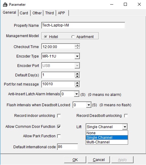
Figure 91
Select the "Lift" dropdown box, and select between Single Channel or Multi-Channel.
- Single Channel – The select lift Floor box is not displayed when issuing Guest cards, Guest cards will by default have lift access to the level that the Guest room resides on.
- Multi Channel – The select lift Floor box is displayed when issuing Guest cards and a Guest card can be issued to access multiple lift levels.
Managing Lift Controller
The elevator controller with power transformer is built into a metal box, this to be fixed on roof top of lift car with AC power supply.
The main control PCB has 16 ports for connection to control the lift push buttons.
There are also connections to the reader which is fixed inside the lift car.
16 ports can control 16 buttons hence 16 levels. If more than 16 level are to be controlled an expansion controller can be added to allow another further 16 outputs. (Up to 64 levels can be controlled via daisy chaining expansion modules)
Integrating / connecting the controller and reader in the lift should be done by qualified lift technicians.
To add the lift controller: Click [Data] then select [Lift Controller] in pull down menu.
[Lift Controller Ports] : ask for the number of ports on the PCB, normally 16 or 32, select with down arrow
[Floors] : number of floors the hotel wants the controller to control, select with up down arrows
[Port] : ask for the starting port number, select with up down arrows
[Floor Order] : floor to be controlled by first port number
After these parameters are set click [Apply], if no need to change anything click [Save]
To change the setting highlight the port number then click [Edit], change as needed then click [Save]
Note: In example Figure 92, PCB has 16 ports, there are 16 levels to be controlled, will use port #1 as starting port and starting the floor is the 1 floor.
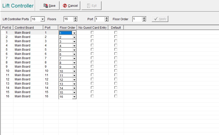
Figure 92
Lift Zone
If so desired a lift zone by grouping levels can be applied. This is different from setting common door zone, the zoning is by levels not by lift.
Click [Data] then select [Lift Zone] in pull down menu.
In the Lift Zone window click [Add], then input the [Code] and [Name] of this zone.
Click the [Select Floor] button at the bottom of the window to popup floor level list, [Select] or [Select All] floors to be included into this zone.
Click [Save] and back to Lift Zone window.
In example Figure 93 a Lift Zone with the name Common Lift Access have been created with Floors 0101, 0102, 0103 and 0117 have been included.
Note: To [Edit] or [Delete] a lift zone, first highlight it in the list then click the corresponding icon.
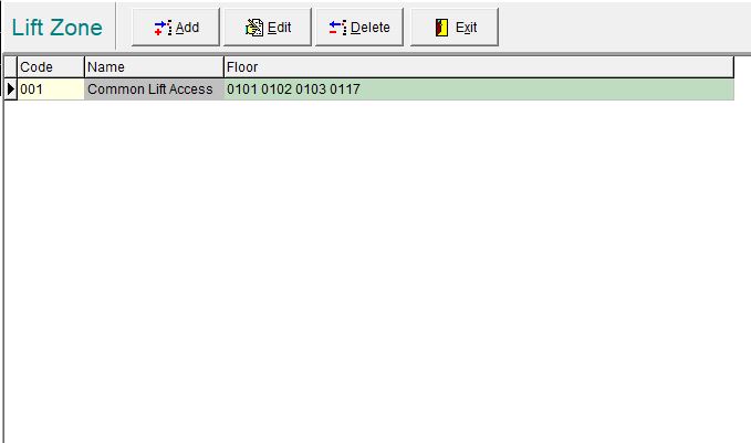
Figure 93
Setting Lift Controller
After the lifts are configured into the system, each lift controller must be encoded to accept valid key cards. Similar to encoding guest room locks, the System Card and Parameter Card are needed.
Since the System Card has been issued in previous section only the Parameter Card for each lift needs to be issued, see section 9.2 regarding issuing Parameter Card. The System Card and Parameter Card must be presented to each Lift Controller reader to complete programming.
Correlate Lift
After configuring and encoding the lift Controllers, users can be given access to lift levels as shown
in Figure 94, select the relevant Lift Level or Lift Zone to give access.
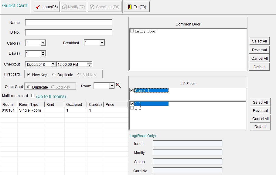
Figure 94
Managing Parking
To prevent unauthorized people from entering the parking lot, an access controller can be integrated with the parking lot barrier.
Enable Parking function
Click [System] then select [System Parameters] in drop down menu and tick the [Allow Park Function]
see Figure 95
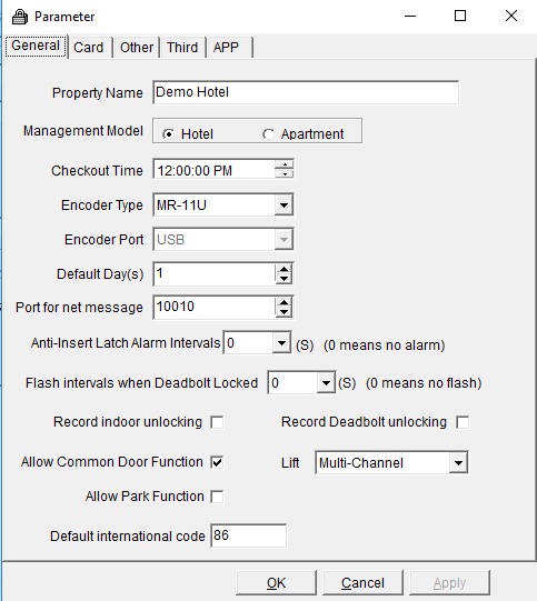
Figure 95
Setting Parking
Parameter Card is needed to encode the parking controller and should be integrated by the parking equipment supplier.
The Parameter card is created similar to the Common door and Lift controller see Figure 96.
Select the [Park] tab, and select the signal time (amount of seconds the relay need to latch for)
Select the Park Device drop-down list, choose the role of the reader, entry exit or both.
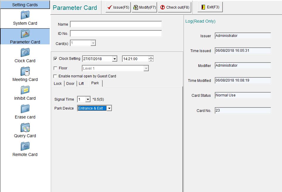
Figure 96
Correlate Parking
After configuring the Parking Controller, guest are given access to the car park by selecting the [Park]
drop-down list and choosing No permission, Can exit, Can entrance or Can Access(Can exit and entrance)
see Figure 97
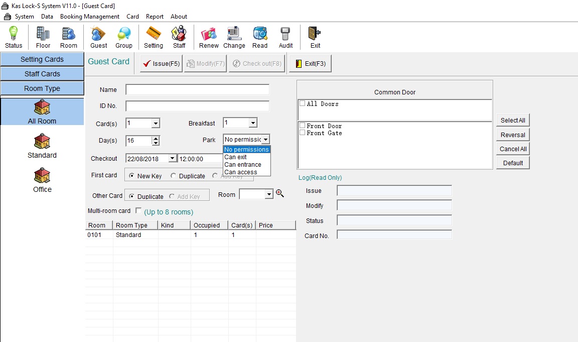
Figure 97
---END---
